Source: Multilink Cubes, Millennium Mathematics Project, maths.org
In the last section, you constructed three-dimensional figures on an isometric grid by using stackable cubes to generate the isometric views of the figures. In this section, you will use different descriptions of objects in order to create isometric views of the objects.
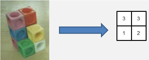
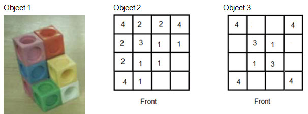
If you have a stack of multilink cubes, such as the ones shown in the picture below, you can represent the figure using a table where the numbers in each cell represent the number of cubes in the stack.
Source: Multilink Cubes, Millennium Mathematics Project, maths.org

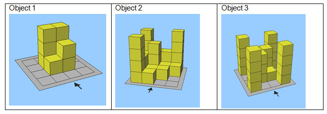
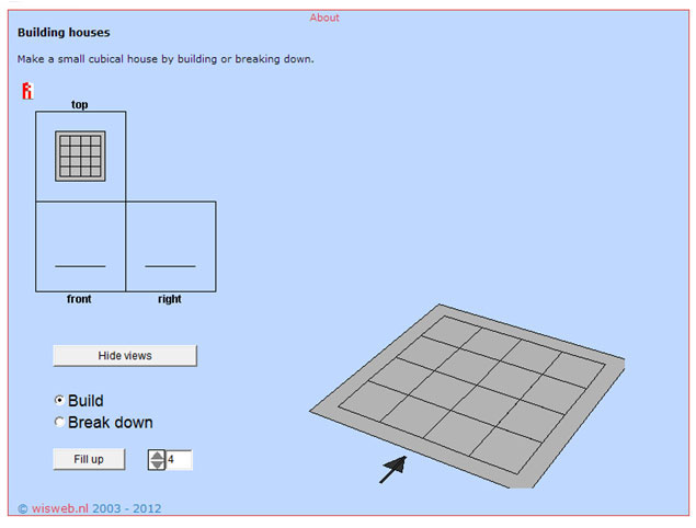
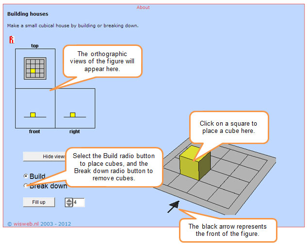
 You will find three objects, including the stack of cubes shown in the picture above, after clicking "Click here for additional instructions" below. Use the Building Houses applet, which is linked to the image below, to build the figure represented by each picture or diagram. Inside of the applet, the black arrow indicates the front of the object. In the diagrams, the number in each square represents the number of cubes that will be stacked in that column.
Interactive popup. Assistance may be required. for additional directions.

Use the information in the interactive you just completed to answer the following questions.
Interactive popup. Assistance may be required.
The number tells you the height of each stack of cubes.
Interactive popup. Assistance may be required.
Your answer may vary, but some students find that the diagram with the height of each stack is easier for complex figures like these than orthographic views. There could be hidden cubes in shorter stacks that are in between taller stacks.
Although there are many applets and other computer-aided design programs that will help you construct isometric views of three-dimensional figures, it is still important for you to understand how to construct these views using isometric dot paper with your pencil or pen.
In both computer and architectural design projects, it is common to draw rough drafts of various perspectives or objects. Using isometric dot paper helps when drawing rough drafts of three-dimensional objects.
Suppose you wanted to draw a rough draft of the three-dimensional figure shown below.
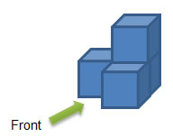
 The video below shows how one designer constructed an isometric view on isometric grid paper of this object.
If you would like to practice using isometric dot paper, you can obtain printable isometric dot paper here (Word document, PDF)
Interactive popup. Assistance may be required.
If the edges were not parallel, then there would be distortion in the isometric view, and we would not know what the figure actually looks like.
Interactive popup. Assistance may be required.
8 cubic inches
Interactive popup. Assistance may be required.
40 cubic inches
You have seen three different ways to represent three-dimensional figures: orthographic views, isometric views, and diagrams with cube heights. For which real-world situations would each representation be most appropriate?
Interactive popup. Assistance may be required.
Orthographic views are useful for real-world figures such as homes or buildings, when you can see the front view, side view, or top view relatively easily. Isometric views are useful when using computer-assisted designs for objects such as aircraft or cars. Diagrams with cube heights are useful when comparing collections of rectangular prisms of different heights, such as a cluster of tall buildings in a particular part of a city or town.
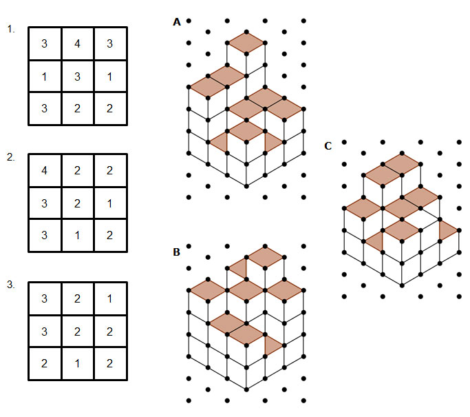
Match each diagram with the isometric view of the figure that it best represents. For each figure, calculate the volume of the figure if each cube has an edge length of 1.5 centimeters.
Interactive popup. Assistance may be required.
What is the volume of one cube? How many cubes would you need to build the figure shown in each diagram?